Coordinate Spaces
Before we can draw a 3D object we need to convert the 3D coordinates to the screen space which is in 2D coordinates. This is done by converting the object’s coordinates with a series of transformations.
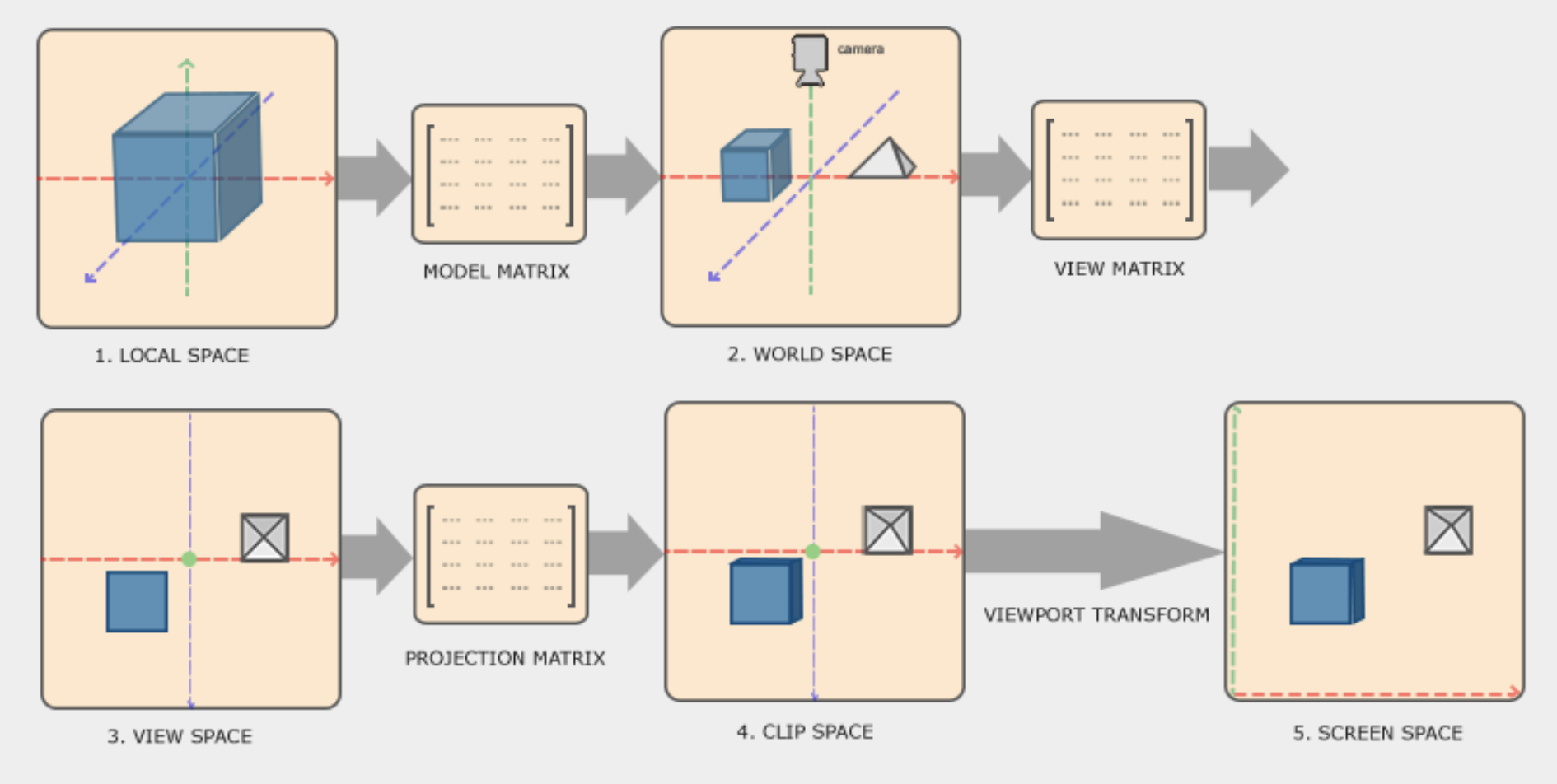
The previous image shows all the different transformations that the object needs to go through before it ends up in the screen.
In this article we will show all the steps.
Local to World Coordinates
We will start by representing the triangle in local 3D coordinates.
// 6 vertices with size 3 each
float vertices[6*3] = {
    -0.5f, -0.5f, 0.0f,
    0.5f,  -0.5f, 0.0f,
    0.5f,  0.5f,  0.0f,
};
This vertices only represent the shape of the object. It does not tell us how big it is or where it is located in the screen.
To transform the object to world coordinates we need create a model matrix that contains the information of location, rotation and scale of the object in the world.
Vec3 position = Vec3{50.0f, 80.0f, 0.0f};
Vec3 rotation = Vec3{0.0f, 0.0f, 0.0f};
Vec3 scale = Vec3{1.0f, 1.0f, 1.0f};
These 3 vectors hold that information but to be able to transform the vertices of the object we need to create a model matrix:
Mat4 model = Mat4_Create();
model = Mat4_Rotate(model, rotation);
model = Mat4_Scale(model, scale);
model = Mat4_Translate(model, position);
We start with an identity matrix that is returned by the Mat4_Create function. Then we apply first the rotation, then the scaling and then the position to the matrix. We will not go into detail on how those functions work here. There are many resources that explain how these transformations with matrices work, like learnopengl.com.
Now that we have a model matrix, we can apply the transformation to each of the vertices:
// Vertices are in local space
for (int i = 0; i < length * size; i += (size * 3)) {
    int v1i = i;
    int v2i = i + size;
    int v3i = i + (size * 2);

    // Convert each vertex to a Vec4 before transformation
    Vec4 v1 = {vertices[v1i], vertices[v1i + 1], vertices[v1i + 2], 1.0f};
    Vec4 v2 = {vertices[v2i], vertices[v2i + 1], vertices[v2i + 2], 1.0f};
    Vec4 v3 = {vertices[v3i], vertices[v3i + 1], vertices[v3i + 2], 1.0f};

    // Model -> World
    v1 = Vec4_Transform(v1, Mat4_Transpose(model));
    v2 = Vec4_Transform(v2, Mat4_Transpose(model));
    v3 = Vec4_Transform(v3, Mat4_Transpose(model));
}
Here we loop over all the vertices and evaluate 3 at a time to draw a full triangle in one go.
World to View Coordinates
The next step is to transform from world coordinates into view coordinates. View coordinates are typically the camera coordinates. The camera is located at some point in the world and looking towards a direction. This transformation moves the object in front of the camera.
First, we need a view matrix:
Mat4 view = Mat4_Create();
view = Mat4_Translate(view, {0.0f, 0.0f, -3.0f});
This is a simple view matrix. Later on we will implement a full camera object that can fly around with the keyboard. Now, we can transform the vertices.
// World -> View
v1 = Vec4_Transform(v1, view);
v2 = Vec4_Transform(v2, view);
v3 = Vec4_Transform(v3, view);
View to Clip Coordinates
The idea of the clip space is to remove/clip all the vertices that are not in the projection of the view/camera. There are 2 main types of projection, orthographic and perspective projection. We will not go into detail here about the differences of those. We will talk more about it when we introduce the camera.
For now we just need a simple perspective matrix to clip our view:
float aspect = (float)r->width / r->height;
Mat4 projection = Mat4_Perspective(DegToRadians(60), aspect, 0.1f, 100.0f);

...

// View -> Clip (Projection)
v1 = Vec4_Transform(v1, projection);
v2 = Vec4_Transform(v2, projection);
v3 = Vec4_Transform(v3, projection);
View to Screen Coordinates
For the next step we need to do 2 different things, a perspective divide to obtain the NDCs (Normalized Device Coordinates), and transform those NDCs to screen space.
The first one is quite simple. We just need to divide every component of the vertex by its perspective component w.
// Clip -> NDC (Perspective Divide)
v1.x = v1.x / v1.w;
v1.y = v1.y / v1.w;
v1.z = v1.z / v1.w;

v2.x = v2.x / v2.w;
v2.y = v2.y / v2.w;
v2.z = v2.z / v2.w;

v3.x = v3.x / v3.w;
v3.y = v3.y / v3.w;
v3.z = v3.z / v3.w;
The idea of the perspective divide is to integrate the w component which carries information of how far objects are from the view. The smaller the object is, the further it is from the screen.
The last step that we need to do is to translate the vertices to the screen coordinates.
float halfWidth = (float)r->width / 2;
float halfHeight = (float)r->height / 2;

...

// NDC -> Screen
v1.x = halfWidth * (v1.x + 1.0f);
v1.y = halfHeight * (1.0f - v1.y);
v1.z = (v1.z + 1.0f) * 0.5;

v2.x = halfWidth * (v2.x + 1.0f);
v2.y = halfHeight * (1.0f - v2.y);
v2.z = (v2.z + 1.0f) * 0.5;

v3.x = halfWidth * (v3.x + 1.0f);
v3.y = halfHeight * (1.0f - v3.y);
v3.z = (v3.z + 1.0f) * 0.5;
Now we have all the vertices of the object in screen space. All we need to do now is draw the triangle.
Note that the z axis contains the information of the depth of each vertex. We will use this later to perform a depth test to display only the vertices that are directly in front of the camera.
